
Visibility splays explained: the UK developer’s guide
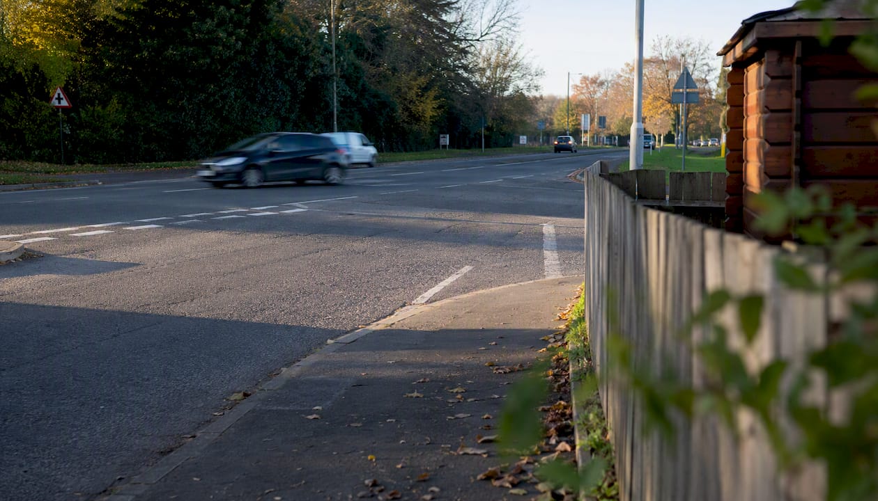
A visibility splay is a triangular zone drawn on a site plan that shows whether a driver emerging from a side road or access can see — and be seen by — traffic on the priority road. Get it right on your drawing and planning officers can check it in minutes. Get it wrong and you’ll be answering queries for weeks.
Before you read any further, here are three things to do right now:
- Measure your X and Y distances. X is the set-back from the carriageway edge (typically 2.4m); Y is the sight distance along the major road, based on the stopping sight distance (SSD) for the speed limit.
- Check the correct SSD for your speed limit. Many UK authorities use established stopping sight distances appropriate for their speed limits, such as commonly used distances for lower-speed streets.
- Confirm who owns the splay land. If any part of the triangle falls outside your client’s ownership, sort that out before you submit.
The three primary references officers reach for are the Manual for Streets (MfS), the Design Manual for Roads and Bridges (DMRB) with its TD9 and TD42/95 standards, and your local highway authority’s own drawing standard, such as the North Somerset visibility splay guidance.
Key takeaways
A visibility splay is a triangular clearance zone defined by an X set-back (typically 2.4m) and a Y sight distance (SSD-based: 25m for 20mph, 43m for 30mph) that must be kept clear in perpetuity and fully annotated on every planning submission.
| Point | Details |
|---|---|
| Definition | A triangular zone showing inter-visibility between minor-road and major-road drivers. |
| X and Y method | X = set-back from carriageway (typically 2.4m); Y = SSD for the speed limit. |
| Typical SSD values | 25m for 20mph streets; 43m for 30mph streets per Southwark and Bristol guidance. |
| Vertical checks | Model eye heights 1.05m–2.0m; keep obstacles clear between 0.6m and 2.0m. |
| Ownership matters | Confirm splay land ownership early; secure clearance in perpetuity via condition or agreement. |
Table of Contents
- What is a visibility splay and why does it matter?
- How do you measure a visibility splay correctly?
- Which UK standard should you use?
- What to show on your planning drawing
- What must be kept clear inside the splay?
- When can you use a relaxation or alternative approach?
- Your planning submission checklist
- A note from Martin
- Sources
What is a visibility splay and why does it matter?
A visibility splay provides the necessary sightlines so that both drivers have sufficient time to react and safely manoeuvre. The driver on the major road needs to see the emerging vehicle before it’s too late to stop. That two-way check is what the term inter-visibility means in practice.
The safety case is straightforward. If a hedge, wall, or parked car blocks the splay, the reaction time available to either driver is reduced, increasing collision risk. Fewer seconds means higher collision risk, and highway authorities treat that risk seriously. Motion’s developer guidance describes visibility splays as “undoubtedly the most important safety component of any priority junction.”
Beyond safety, splays affect capacity. A junction with poor visibility forces drivers to creep forward, slowing traffic on the major road and reducing the effective capacity of the access. That matters on busier routes and on sites with high vehicle movements.
Authorities don’t just want the splay to be clear on the day of the site visit. They expect it to stay clear permanently. That’s why planning conditions, adoption agreements, and maintenance covenants exist — and why you need to think about ownership from day one.
How do you measure a visibility splay correctly?
The method uses two distances: X (the set-back) and Y (the sight distance). Here’s how to work through it on plan.
- Locate the X point. Measure X back from the nearside edge of the major carriageway along the centre line of your access. The standard value is 2.4m for most residential and urban accesses. For major/minor priority junctions under DMRB, the desirable X is 9m, with relaxations to 4.5m or 2.4m in difficult circumstances.
- Measure Y in both directions. From the X point, measure Y along the nearside edge of the major road to the left and to the right. Y equals the SSD for the design speed of that road.
- Draw the sight lines. Connect the X point to each Y point. The two lines and the edge of the carriageway form a triangle on each side. That triangle is the splay.
- Check for obstructions. Anything inside the triangle that rises above 0.6m could block sight lines. Clear it, or show it can be cleared.
Typical X and Y values for common speed limits
| Speed limit | X distance | Y distance (SSD) |
|---|---|---|
| 20mph | 2.4m | 25m |
| 30mph | 2.4m | 43m |
| Higher speeds (DMRB) | 9m desirable | Derived from TD9 SSD tables |
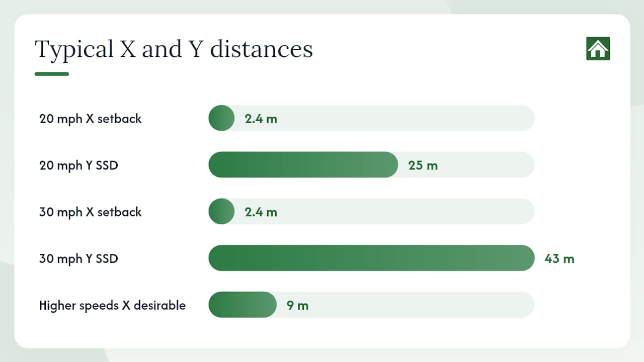
Southwark Council’s highway visibility guidance and Bristol City Council’s visibility guidance both use 25m for 20mph and 43m for 30mph as their standard Y distances.
Vertical-plane checks
Plan sight lines alone aren’t enough. You also need to check the vertical plane. Model driver eye heights between 1.05m and 2.0m above the carriageway. Obstacles inside the splay must be clear between 0.6m and 2.0m above footway level. Where speeds exceed a higher threshold, the clearance height is reduced appropriately to a lower value. If the splay crosses raised ground, a kerb, or an embankment, produce a long section to show the vertical clearance.
Pro Tip: Vertical-plane failures are easy to miss on a flat drawing. Always model the cross-fall and any level changes across the splay, especially where a footway is raised relative to the carriageway.
Which UK standard should you use?
Choosing the right document depends on the road type and speed environment. Here’s a plain summary.
Manual for Streets (MfS1 and MfS2) covers residential and lightly trafficked urban streets. Use MfS-style criteria for lower-speed, built-up contexts. Manual for Streets 2 is explicit that much of the SSD research behind earlier guidance applies primarily to traffic speeds under 40mph, and it cautions against copying trunk-road SSD figures into low-speed residential streets.
DMRB / TD9 / TD42/95 applies to higher-speed roads, trunk roads, and dual carriageways. TD42/95 sets out the X/Y conventions for major/minor priority junctions in detail, including the desirable 9m X distance and the SSD-based Y distances. Use DMRB where the operating speed or road classification takes the site out of MfS territory.
Local authority drawing standards sit on top of both. Always check what your specific highway authority requires. North Somerset, Southwark, Bristol, and Nottinghamshire all publish their own guidance, and officers will expect your submission to match their preferred format and figures. When in doubt, ring the highway development management team before you draw anything.
For statutory questions about adoption, highway orders, or formal dedication of land, Legislation is the authoritative source for the relevant Acts and statutory instruments.
What to show on your planning drawing
A well-labelled drawing saves everyone time. Officers can check it quickly, and you avoid the back-and-forth of information requests. Here’s what to include.
Plan view essentials:
- Clearly labelled X distance with the set-back point marked (e.g. “X = 2.4m from nearside carriageway edge”)
- Y distances labelled on both sides (e.g. “Y = 43m — 30mph SSD”)
- Left and right sight lines drawn to form the triangular splay
- Scale bar and north point
- A note of the assumed driver position and speed limit
Vertical-plane statement:
- State the driver eye-height range used (e.g. “Eye height modelled at 1.05m–2.0m above carriageway”)
- State the obstacle clearance height (e.g. “Splay to be kept clear of obstructions between 0.6m and 2.0m above footway level”)
- Include a long section if there are level changes across the splay
Ownership and maintenance note:
Show whether the splay falls within the highway, on land to be dedicated, or on private land. A short annotation works well here. Something like: “Visibility splay to be kept clear of obstructions between 0.6m and 2.0m above footway level in perpetuity. See planning condition / maintenance agreement ref: [X].”
| Drawing element | What to show |
|---|---|
| X point | Distance from carriageway edge, marked on plan |
| Y distances | SSD value, speed limit, both directions |
| Sight lines | Left and right triangles clearly drawn |
| Vertical statement | Eye heights and obstacle clearance range |
| Ownership note | Highway, dedicated land, or private with agreement |
What must be kept clear inside the splay?
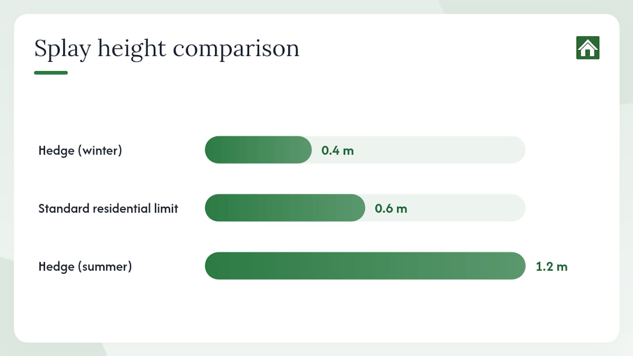
Common obstructions include boundary walls, close-boarded fencing, hedges, parked vehicles, bins, and street furniture. Any of these can block a sight line even when the plan looks fine. Hedges are particularly tricky because they grow, and a hedge that’s 0.4m tall in winter can be 1.2m by August.
The standard maximum height inside most residential splays is 0.6m. Anything above that is treated as an obstruction. For higher-speed roads, the threshold is lower still.
Authorities secure splays in several ways. The most common are:
- Planning conditions requiring the splay to be kept clear before first use and maintained thereafter
- Dedication to the highway so the land becomes part of the public highway and the council maintains it
- Legal agreements with neighbours where the splay crosses land in third-party ownership
- Adoption as footway where the splay area is surfaced and taken into highway maintenance
Councils commonly treat splay land as needing to stay clear in perpetuity, so plan for a formal arrangement rather than relying on a neighbour’s goodwill. If the splay crosses land outside your client’s ownership, begin boundary negotiations early. You may need to dedicate the land to the highway or secure a maintenance covenant as part of the application. For developers coordinating highway works alongside this, S278 agreements are often the mechanism used to formalise those obligations.
Pro Tip: Check the corner log cabin boundary planning rules article if your project involves a building close to the boundary — the ownership principles are closely related.
When can you use a relaxation or alternative approach?
Not every site fits the standard template. Here are the most common special cases and what officers expect to see.
- X-distance relaxation. TD42/95 allows X to reduce from 9m to 4.5m, or in exceptional circumstances to 2.4m. Southwark permits a reduced X on 20mph streets in some cases. Always justify the reduction in writing.
- Curved streets. Sight lines on a bend need to follow the curve of the road, not a straight line. Show this clearly on the drawing and confirm the Y distance is measured along the road alignment.
- Dual carriageways. Where a central reserve shelters turning traffic, the left-hand splay may not be required. Confirm this with the highway authority in writing before removing it from the drawing.
- One-way streets. Only one direction of travel applies, so only one splay is needed. State the direction of travel clearly on the drawing.
- Lightly trafficked accesses. For a simple access with very low vehicle movements, some authorities accept a reduced Y distance. You’ll need traffic data and accident records to support this.
Whatever the relaxation, get a formal written agreement or recorded departure from the highway authority before assuming it will be accepted. A verbal conversation is not enough.
Your planning submission checklist
Copy this into your submission notes and tick each item before you send.
- [ ] Plan view with X and Y distances clearly labelled
- [ ] Left and right sight lines drawn, forming the triangular splay
- [ ] Speed limit and SSD value stated and justified
- [ ] Vertical-plane statement: eye heights (1.05m–2.0m) and obstacle clearance (0.6m–2.0m)
- [ ] Long section provided where level changes cross the splay
- [ ] Ownership of splay land confirmed and annotated
- [ ] Maintenance note or planning condition wording included
- [ ] Photographs of existing sight lines from the X point
- [ ] Swept path analysis for large vehicles where relevant
- [ ] Speed survey included if the existing road speed is uncertain
- [ ] Scale bar and north point on all drawings
- [ ] Local highway authority drawing standard checked and followed
Common errors to avoid: missing the vertical-plane statement, leaving X and Y unlabelled, submitting no maintenance note, and assuming neighbouring land will be available without a formal agreement.
For projects where planning permission is also needed for a garden building on the same site, check that the cabin’s position doesn’t itself become an obstruction inside the splay.
A note from Martin
Visibility splays look simple on paper, but the problems almost always come from the same two places: ownership and vertical checks. I’ve seen applications stall for months because the splay crossed a neighbour’s hedge and nobody had spoken to them. The fix is easy — talk to the highway officer and the neighbour early, before the drawing is even started.
On the drawing itself, annotate your assumptions clearly. State the eye height, state the obstacle height, state the SSD and why you’ve chosen it. Officers appreciate drawings that explain their own logic. It reduces queries and speeds up decisions.
One practical shortcut: take photographs from the X point in both directions and annotate them with the sight-line distances. A photo tells an officer more than a plan view alone, and it shows you’ve actually visited the site. Also check hedges in summer, not just winter. A hedge that looks fine in February can fail the splay by June.
If you’re using MfS criteria, make sure the road genuinely fits that context. Manual for Streets 2 is clear that its SSD research applies to speeds under 40mph. Applying MfS figures to a 40mph road without justification is the kind of thing that gets picked up in technical review.
Sources
These are the documents worth bookmarking before you start any access or junction design.
Manual for Streets (MfS1) — the primary reference for residential and urban streets. Sets out SSD-based Y distances and the X set-back method for lower-speed contexts.
Manual for Streets 2 (MfS2) — extends MfS1 and adds important caveats about SSD research being limited to speeds under 40mph. Read this before choosing between MfS and DMRB.
DMRB TD42/95 — the standard for major/minor priority junctions on higher-speed roads. Defines the desirable 9m X distance, permitted relaxations, and SSD-based Y distances.
DMRB TD9 — covers stopping sight distance on higher-speed roads. Use the SSD tables here when TD42/95 applies to your site.
North Somerset drawing standard — a clear, practical example of what a local authority expects on a visibility splay drawing. Useful even if you’re working in a different authority area.
Southwark Council highway visibility guidance — detailed on X/Y values, vertical-plane heights, and submission requirements.
Bristol City Council visibility guidance — covers both horizontal and vertical checks, pedestrian inter-visibility (2m x 2m splay to the back edge of footway), and SSD examples.
Nottinghamshire County Council visibility splays guidance — explains the X/Y measurement conventions clearly and is a good reference for the basic method.
legislation.gov.uk — for statutory instruments and Acts relating to highway adoption, dedication, and highway orders.
Always check your own local highway authority’s advice note or drawing standard alongside these national references. Figures and submission formats vary between councils, and officers will expect you to follow their preferred approach.
- Drawing standard - visibility splay | North Somerset Council
- Highway visibility | Southwark Council
- Visibility guidance | Bristol City Council